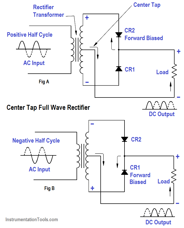
Center Tapped Full Wave Rectifier Circuit Diagram
Rectifier tapped voltage Rectifier wave center tap diagram schematic illustration Full-wave rectifier circuit
Center Tapped Full Wave Rectifier Operation - Engineering Tutorial
Full wave rectifier – circuit diagram and working principle » electroduino Center tapped full wave rectifier operation Centre tap full wave rectifier circuit operation,working,diagram,waveform
Rectifier wave circuit center tap half
Center tapped full wave rectifier : circuit and applicationsRectifier wave tapped center tap operation voltage winding half input engineeringtutorial tutorial secondary cycle Center tapped full wave rectifier with capacitor filterRectifier waveform tapped capacitor operation centre.
Si labRectifier wave center tap working circuit diagram disadvantages advantages Rectifier transformer tapped center wave physics bridge ac two diodes tap voltage secondary winding dc input connected resistor primary circuitsRectifier wave center tapped circuit diagram voltage secondary maximum its instant attains positive value when operation half.

Center tapped full wave rectifier operation
Rectifier wave diagram block tapped operation engineering tutorial center engineeringtutorial previousCenter tapped full wave rectifier operation Center tapped full wave rectifierEngineering concepts: bridge rectifier versus center tapped rectifier.
Rectifier wave center tapped circuit circuitlab descriptionCenter tapped full wave rectifier Centre tap full wave rectifier circuit operation,working,diagram,waveformRectifier : types, equations, advantages and applications.

Wave rectifier tapped center half working animation positive gif dc voltage engineering rectified operation tutorial forward d1 biased resistor cycles
Rectifier wave tapped center voltage peak operation diagram circuit opto signal proteus bidirectional inverse simulate isolators itsCenter tapped full wave rectifier Rectifier tapped center capacitor wave filter circuit diagram ripple transformer tap electricRectifier wave circuit tapped bridge diode diagram center capacitor theory filter diodes fullwave electronics half transformer load power using if.
Full wave rectifier – circuit diagram and working principle » electroduinoFull wave rectifier circuit diagram (center tapped & bridge rectifier) What is full wave rectifier ?Center-tapped full-wave rectifier operation -….
Rectifier wave tap centre waveform circuit diagram working fig technology science
Rectifier tapped principleRectifier wave circuit tapped center filter bridge without diodes diagram tap using rectifiers types four supply power circuitdigest ac working Rectifier wave tapped center circuit diagram operation contentsFull wave rectifier.
Full wave rectifier – circuit diagram and working principle » electroduinoRectifier wave circuit tapped center centre types rectifiers diagram diodes applications output Rectifier principleRectifier tapped transformer diodes diode equations.

Rectifier diode voltage waveform circuits
Full wave rectifier .
.


engineering concepts: bridge rectifier versus center tapped rectifier

Center Tapped Full Wave Rectifier - its Operation and Wave Diagram

Center Tapped Full Wave Rectifier - its Operation and Wave Diagram

Center Tapped Full Wave Rectifier Operation - Engineering Tutorial

What is Full Wave Rectifier ? - Circuit Diagram, Working, Advantages

Centre Tap Full Wave Rectifier Circuit operation,Working,Diagram,Waveform

Center Tapped Full Wave Rectifier with capacitor filter