Control Valve Circuit Diagram
Bypass flow control circuit – manufacturinget.org Iso schemes of directional control valves Arduino solenoid valve controlling breadboard connecting through
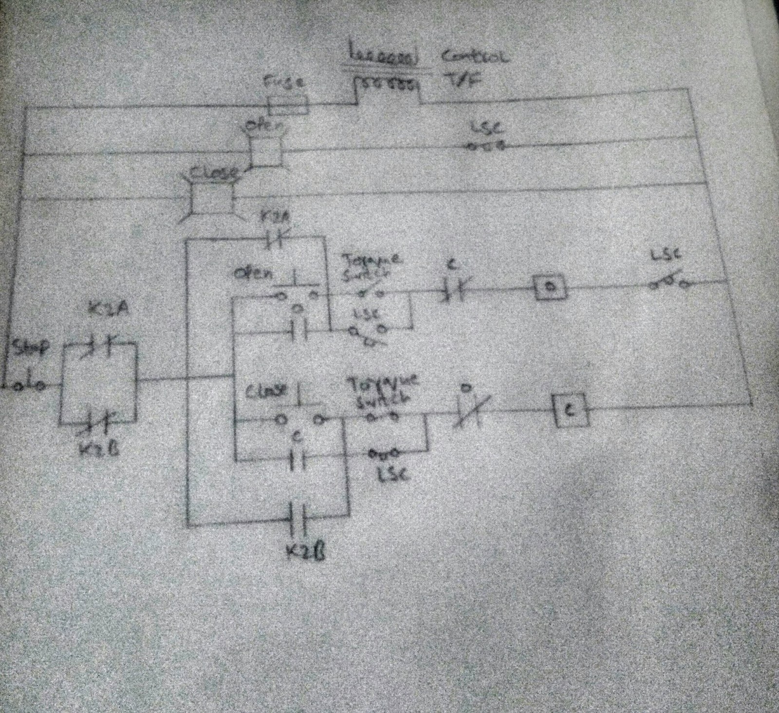
Control circuit of the electric valve
Control circuit of the electric valve Control valve positioner circuit diagram Uk vintage radio repair and restoration
Motor simplified rig efficiency valve piston directional
Schematic hydraulic valve control directional pneumatic drawing engineering symbol mechanical parts equipment diagram pump flow solenoid valves reservoir spring motor32: electrical diagram of the pneumatic valve controls Controlling a solenoid valve with arduinoFreely electrons: circuit diagram of motor operated valve.
Pneumatic 5-ported 3-position valve templateManual operated directional control valve Diagram engine diesel energies pv petrol oil stroke engineering space system g001 lube main valve combination cfd text combustion validationCircuit diagram for connecting the solenoid valve with the.

Sequence valve circuits actuator single pressure development circuit ppt diagram powerpoint presentation pneumatic
Solenoid circuit driver diagram circuits dc valve control coil current board electronic will electronics projects complete understand taking once designedValve considerations specifying valves Regulation valve automaticAutomatic valve regulation circuit..
Schematic diagram of a control valve.Solenoid driver circuit diagram Circuit diagram motor valveRogers rd cadet mk 3 stereo amplifier circuit diagram and operating.

Valves way control directional iso pneumatik cylinder exhaust
Amplifier pcb valves flow control 12au7 tube circuit valve layout ic booster caster ts idea bigValve motorized wiring diagram control cr2 Continuously controlledSolenoid valve control using arduino.
Continuously-controlled valve schematic.Key considerations in specifying control valves Using a proportional pressure control as a directional control valvePcb booster tube and light flow control valves using 12au7.

Directional operated hydraulic
Limit switches upravlenieSimplified hydraulic circuit schematic for the motor efficiency test Valve radio vintage work valvesSolenoid circuit microcontroller relay.
Solenoid 12v controlling 24v mechatroficeCircuit flow control bypass cylinder manufacturinget position demonstrations procedure Control valve directional circuit pressure proportional using hydraforce would traditonalDiagram circuit unit control amplifier rogers cadet stereo rd radio operating mk manual valve.
Control valve
Valve control actuator pneumatic diagram schematic air citizendium milton pd main pressureCombination valve diagram Valves actuator positioner instrumentation functions instrumentationtools principle breather understanding boilerControl valve.
Schematic diagram of the flow control valveSchematic diagram of 3-way control valve for precision temperature Motorized valve wiring diagram cr2 01 wiring controlScheme of control valve.


Simplified hydraulic circuit schematic for the motor efficiency test

ISO Schemes of directional control valves

Rogers RD Cadet MK 3 Stereo Amplifier Circuit Diagram and Operating

Circuit diagram for connecting the solenoid valve with the

Using a Proportional Pressure Control as a Directional Control Valve

Automatic valve regulation circuit. | Download Scientific Diagram

Control circuit of the electric valve