Dc Dc Buck Boost Converter Circuit Diagram
Dc converter circuit buck 5v diagram 3a charger battery mobile step smartphone 555 timer converter ne555 35v circuits simples conversor usando how2electronics Buck converter boost circuit voltage circuits power dc ac diagram supply gr next torrents battery
Get Torrents From My Blog: BUCK BOOST CONVERTER CIRCUIT
Dc boost converter circuit 3.3-5v to 12v-13.8v Is there a universal tool for dc/dc voltage conversion? Dc to dc boost converter circuit using 555 (tutorial :
Buck boost converter dc circuit theory electronoobs circuitos
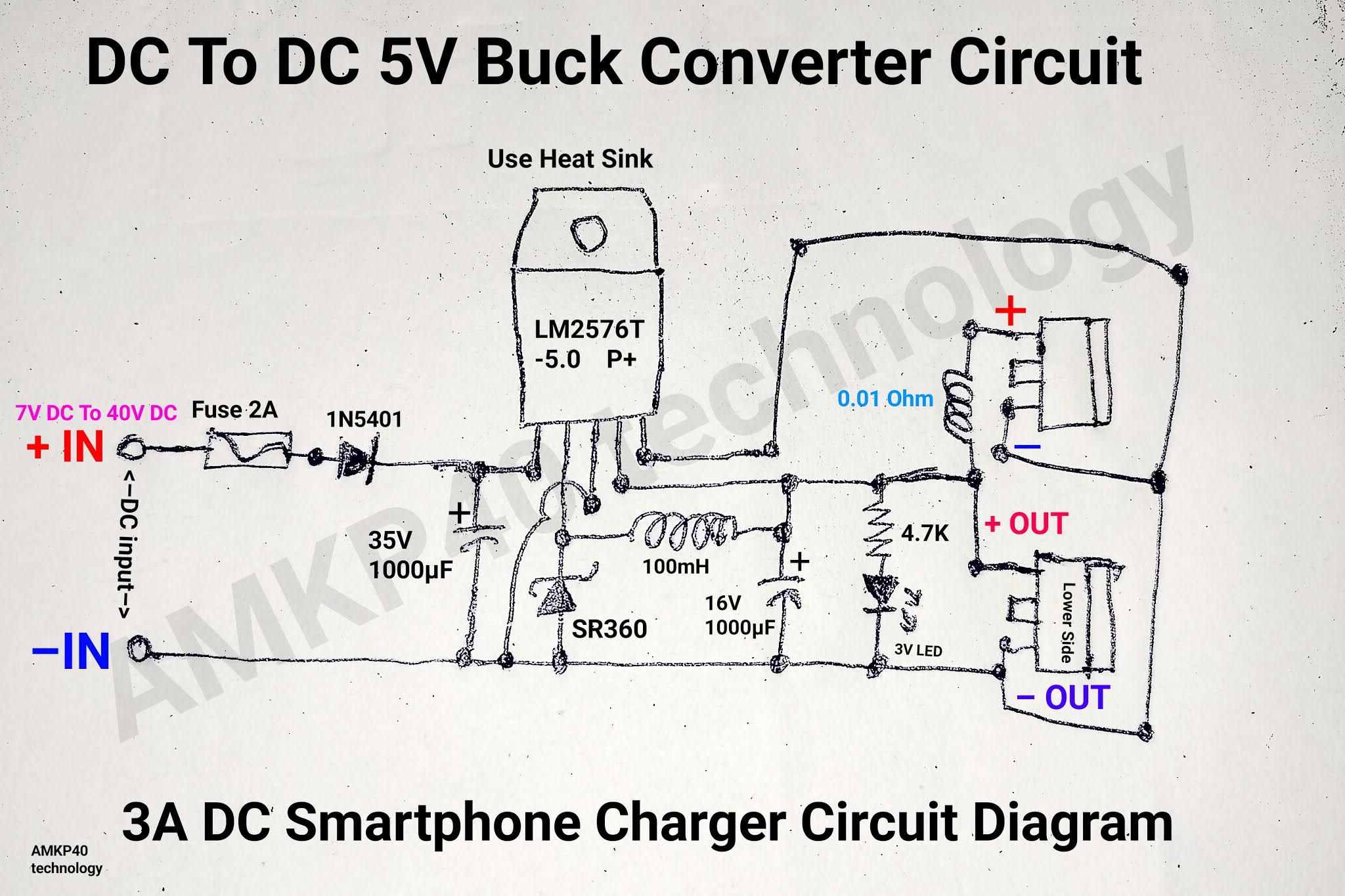
Dc to dc buck converter [adjustable, 97% efficient, 3a]Buck voltage conversion ti Buck boost converter dc current circuit will formulas inductor reduced opened switch when circuitos electronoobsDc to dc 5v 3a buck converter circuit diagram, or 3a dc smartphone.
Buck bidirectional implement studied literatureDc to dc buck-boost converter circuit homemade Analysis of four dc-dc converters in equilibriumSwitch mode power supply.

Dc converter buck boost module lm2596 lm2577 modules
Buck boost theorycircuitDc converter boost circuit 555 using tutorial kaynak Designing an arduino-based buck-boost converter with feedbackBoost converter using ir2110 and pic microcontroller.
Converter buck circuit boost dc diagram converters analysis equilibrium four output positive articles figureConverter buck boost arduino feedback based maker pro How to build a dc-to-dc boost converter circuitSimple dc-dc converter using 555 timer ic (7.5-35v).

Converter boost microcontroller ir2110 using pic dc circuit microcontrollerslab schematic diagram voltage proteus pwm variable power mosfet based supply current
Converter buck circuit boost dc diagram ac converters working analysis equivalent theory applications evaluation equilibrium articles allaboutcircuits modelling four switchingDc to dc buck-boost converter circuit homemade Converter buck dc 3a adjustable efficient schematic diagram step down figureDc to dc buck-boost converter circuit homemade.
Converter boost circuit dc 5v 12v diagram 8v step 7v power eleccircuit 24v simple output 6v using 24vdc convert inputBuck boost converter dc circuit arduino pwm schematic electronoobs nano voltage homemade circuits regulator potentiometer circuitos Converter inductor breadboardLtc3442 buck boost converter circuit.

Dc/dc buck-boost converter block diagram
Dc-dc boost buck converter module ( lm2596 lm2577 )Buck boost converter circuit theory working and applications Get torrents from my blog: buck boost converter circuit.
.

ltc3442 buck boost converter circuit - theoryCIRCUIT - Do It Yourself

Simple DC-DC Converter using 555 Timer IC (7.5-35V)
.png)
Buck Boost Converter Circuit Theory Working and Applications

Boost converter using IR2110 and pic microcontroller

DC Boost Converter circuit 3.3-5v to 12V-13.8V - Eleccircuit

DC-DC Boost Buck Converter Module ( LM2596 LM2577 ) - EEEShopBD
![DC to DC Buck Converter [Adjustable, 97% Efficient, 3A] - Technology](https://i2.wp.com/pcbwayfile.s3-us-west-2.amazonaws.com/web/19/10/28/1132491215162t.jpg)
DC to DC Buck Converter [Adjustable, 97% Efficient, 3A] - Technology
.png)
Analysis of Four DC-DC Converters in Equilibrium - Technical Articles