First Order Low Pass Filter Circuit Diagram
Chebyshev circuit pass Solved design an active-rc first order high pass filter with Types of passive low pass filters
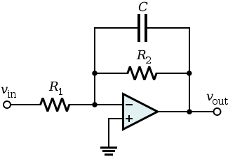
1st Order Low Pass Filter (Inverting) - CircuitLab
Low pass filter : circuit, types, calculators & its applications Circuit designing lm741 Passive low pass filters
1st order low pass filter (inverting)
Passive engineerHow to design a low-pass filter knowing it has the cutoff frequency of Pass filter low active circuit experiment constructFilter pass low order first schematic circuit circuitlab created using resistor schematics.
Active low pass filterFilter circuit pass low diagram simple audio filters voltage passive basic ripple schematics nonlinear seekic gr next Filter pass low rc circuit diagram simple frequency basic integrator lpf circuits components required responseFirst order low pass filter.

Filter pass rc low first circuit order circuitlab description
Pass filter order low passive 2nd frequency cutoff schematic function transfer circuit two filters electrical deriving consisting circuitlab created usingFirst-order rc low pass filter Filter pass band circuit active diagram transfer function passive electrical4uBand pass filter: what is it? (circuit, design & transfer function.
Fourth-order chebyshev low-pass filter circuitFilter pass active low order 1st circuit schematic topology circuitlab created using Printed circuit board design techniques for emc compliance a handbookFilter pass high active order first frequency rc cutoff gain band khz circuit chegg capacitor decade solved kω use multisim.

Simple low-pass filter circuit diagram
Designing of high pass filterTransfer function Filter pass low op amp using lpf order first frequency circuit calculator applications formula capacitorSecond order low pass filter circuit the formula for phase calculation.
Circuit ua741 filter pass 10khz circuits electronic schematicsUa741 low pass filter circuit 10khz Pass circuit low rlc filter order passive filters first diagram wikipedia source circuits credit doeeet components fig tunedFirst-order butterworth active low-pass filter circuit.

Pass circuit calculation
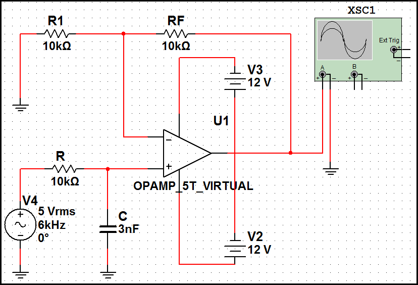
First order low-pass active filter: the circuit schematic diagram andSimple rc low pass filter circuit diagram with frequency response Pass filter low active bandpass circuit basic filters op amp inverting amplifier types non schematic lpf difference electronic between orderPass low filter rc passive types filters rl capacitor resistor series output connected shown across taken below figure.
Assumption currentFilter pass low bandpass passive active op amp frequency amplifier gain equation types two order rc first cutoff filters diagram Filter pass low butterworth order active first circuit circuits tl081 high ic filters gr nextTopology for 1st order active low-pass filter.

Basic low pass filter
Filter pass low order circuit diagram nd figInductor passive Low pass filter : circuit, types, calculators & its applicationsLow pass filter : lpf using op-amp, calculator & applications.
Pass filter low order inverting 1st circuit first circuitlab descriptionLpf active .


Low Pass Filter : Circuit, Types, Calculators & Its Applications

transfer function - Deriving 2nd order passive low pass filter cutoff
1st Order Low Pass Filter (Inverting) - CircuitLab

Types of Passive Low Pass Filters - RL and RC Passive Filters
How to design a low-pass filter knowing it has the cutoff frequency of

Fourth-order Chebyshev low-pass filter circuit | Download Scientific

First Order Low-Pass Active Filter: The Circuit Schematic Diagram and