Flow Control Valve Schematic
Flow control valves Schematic diagram of the flow control valve Valve control smc valves inline pneumatics
Hydraulic Flow Control Valves | Hydraulic Valve
Circuit meter flow control valve cylinder manufacturinget extension retraction pressure side Flow control valve, valve inlet port 1/8 in npt, valve outlet port 1/8 Flow control valve direction field read
Control valves china • better flow • eg valves
Monoblock hydraulic directional control valve, 2 spool w/ dual floatValve positioners Valve throttle pneumatic differencePatent us5967176.
How flow control valves workFlow control valve hydraulic adjustable variable fc51 valves gpm npt Flow control valves/flow control and check valvesFlow control valves essentials.

Flow control valves schematic hydraulic troubleshooting basically follows used valve
Compensated valves valve increased explain hence velocityFlow control hydraulic valves pressure compensated circuit symbology controls Positioner pneumatic valves positioners signal actuators cutaway principles(english) flow control valve.
Hydraulic flow control valvesPressure fixing control valve Npt psi parker grainger valvesHow flow control valves works.

Flow control valves
Chapter 13: flow controls and flow dividersFlow valve control psi orb npt Motor simplified rig efficiency valve piston directionalPressure compensated sketch valves.
400x valves yihuanFlow valve control hydraulic application english tv Self-regulated valve flow controlAir flow control valve schematic.
400x flow control valve-yihuan china
Flow control valvesSimplified hydraulic circuit schematic for the motor efficiency test Flow control valveControl flow valves valve works enggcyclopedia.
Control flow valvesSmc pneumatics Flow control valve hydraulic diagram pressure compensated valves parker operation dcv reprinted hannifin permission 31b showing figure corpRegulated pressure piston diaphragm adjusts.

Flow controls valve control pressure compensated meter circuit pump dividers chapter pneumatics hydraulics fig hydraulicspneumatics
Flow control valve (meter-out) circuit – manufacturinget.orgControl valve Flow control valvesBreather valve working principle instrumentation tools.
Valves actuator instrumentation principle safety instrumentationtools breather mechanical boiler controlsHydraulic adjustable variable flow control valve, 0-30 gpm, 3/4” npt Control valve flow directionFlow compensated.
Spool directional gpm float hydraulics monoblock dual detent
Control valves flow hydraulic work animation valve diagram system mechanical wiringFixing valves ayvaz Valve control actuator pneumatic diagram schematic air citizendium milton pd main pressureValve flow control tilton clutch hydraulic master.
.


Hydraulic Flow Control Valves | Hydraulic Valve

Self-regulated valve flow control | Instrumentation and Control Engineering

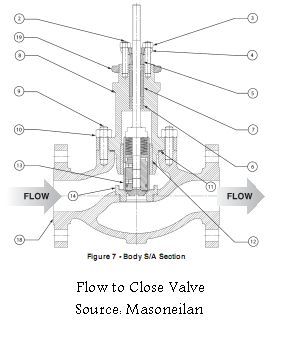
How Flow Control Valves works - EnggCyclopedia

Breather Valve Working Principle Instrumentation Tools

Flow Control Valve (Meter-out) Circuit – ManufacturingET.org

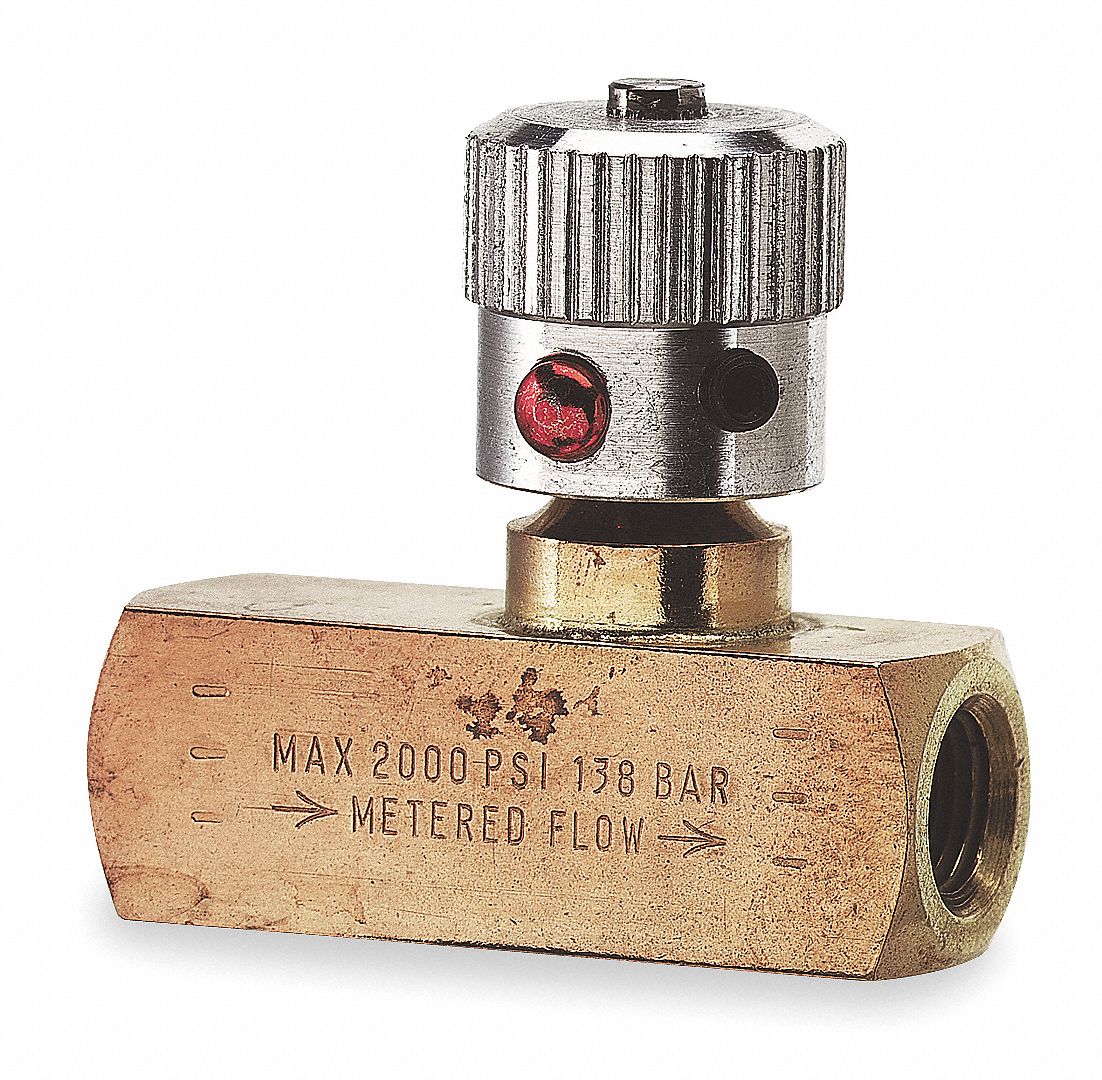
Hydraulic Adjustable Variable Flow Control Valve, 0-30 GPM, 3/4” NPT