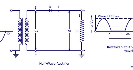
Half Rectifier Circuit Diagram
Full wave bridge rectifier ckt diagram Rectifier half phase controlled rl current Rectifier & half wave rectifier circuit bangla tutorial
Draw the Circuit Diagram of a Half Wave Rectifier and Explain Its
Rectifier working explain shaalaa diode junction Rectifiers rectifier circuits Solved the following schematic is a rectifier circuit that
Basics of half wave rectifier
Inrush resistor schematicRectifier wave circuit output waveform input Onclick786: rectifier,half wave rectifiers,half wave rectifier withRectifier capacitor dc rectifiers pulsating capacitive.
Rectifier wave half positive engineering stackRectifier wave circuit Draw the circuit diagram of a half wave rectifier and explain itsPrecision rectifier circuit using opamp working and applications.
Single phase half wave controlled rectifier with rl load
Rectifier circuit diagramRectifier circuit wave half transformer examples step using down voltage spice peak rms ratio turns fig Rectifier circuit opamp silicon diode 7vRectifier dc ckt transformer converting.
Half wave rectifier and circuit diagram and working principleScience and technology: rectifier Half wave rectifier circuit with/without filterRectifier wave half circuit diagram voltage transformer secondary gif principle working applied where.

Explain working of rectifiers circuits
Rectifier half circuit wave theory diodeRectifier controlled voltage conducts applied across Wave half rectifier capacitor filter circuit diagram output waveform rectifiers diode bridge using transformer resistor rc operation working diodes usedRectifier circuits.
Rectifier wave half circuit filter without diagram capacitor circuits circuitdigest voltage breadboard 7uf ripple hence reduced gets halfwaveThree phase half controlled rectifier Half wave rectifierVedupro: rectifier circuit, rectifier theory, half wave rectifier, full.

Power supply design notes: rectifier circuits
3.4 a half-wave rectifier circuit .
.


Solved The following schematic is a rectifier circuit that | Chegg.com

Rectifier Circuit Diagram | Half Wave, Full Wave, Bridge - ETechnoG

Draw the Circuit Diagram of a Half Wave Rectifier and Explain Its

Single Phase Half Wave Controlled Rectifier with RL Load - Electrical

rectifier - Could this resistor be intended to do anything other than

Precision Rectifier Circuit using OPAMP working and applications

Three phase Half controlled rectifier | Electronics Tutorial

Full Wave Bridge Rectifier Ckt Diagram - PCB Designs