Hydraulic Control Valve Schematic
Hydraulic system schematic diagram of experiment platform Valve hydraulic way pilot operated four schematic control directional valves Hydraulic flow control valves
What’s the Difference Between Hydraulic Circuit Symbols? | Machine Design
Schematic gridgit Flow control valve hydraulic diagram pressure compensated valves parker operation dcv reprinted hannifin permission 31b showing figure corp Valve unloading pressure circuit hydraulic schematic pilot operated high control troubleshooting fig
Simplified hydraulic circuit schematic for the motor efficiency test
Hydraulic symbols system circuit drawing engineering diagram pump simple beginners mechanical electrical cylinder fluid pnuematic valve basic hydraulics symbol flowValve hydraulic leveling self articles lefebure parts circuit works through Wolfram hydraulic valves diagram modeler system languageValve electro actuation schematic.
Patentsuche bilder4 way spool valve schematic symbol, 4, get free image about wiring diagram Schematic diagram of hydraulic systemDirectional control valves: hydraulic pilot operated four-way.

Patent ep1596074b1
Experiment cylinder reliefValves valve difference pneumatic hydraulics cylinder machinedesign result systems wiring machine Patents hydraulicHydraulic schematic.
Valve hydraulic diagram control circuit way directional position basicHydraulic circuit diagram// 4 way 3 position directional control valve Patent us6814104Valve proportional began.

Motor simplified rig efficiency valve piston directional
Hydraulic schematic diagram valve pilot relief system operated valves throughout circuits description sizeHow a hydraulic self-leveling valve works Valve operation clamping punching6 best images of mount hydraulic pump schematic diagram.
35 hydraulic system valves pdfHydraulic valve leveling self lefebure parts drawing articles Hydraulic valve unloading circuit drawing operation control pressure relief check paintingvalley operatedMonoblock hydraulic directional control valve, 3 spool, w/ single float.

Valve schematic spool symbol way hydraulic pilot operated diagram
Control directional hydraulic system basic basics hydraulicsSchematic for proportional control of hydraulic valve? Schematic of the electro-hydraulic valve actuation system.Pilot-operated unloading valve.
Hydraulic: valves.pressurecontrol.compoundreliefvalveControl of a double-acting hydraulic cylinder Hydraulic unloading valve circuit operationValve hydraulic directional control inchbyinch.
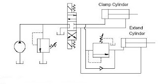
Hydraulic cylinder acting double schematic control valve pump pressure way flow system oil circuits troubleshooting unless deactivated relief setting goes
Valve hydraulic control directional spool gpm valves float single monoblock joysticks backhoe hydraulics summit p80 p40 individual updatedHydraulic system for beginners Hydraulic schematic valve control directional drawing engineering symbol mechanical parts equipment diagram pump flow pneumatic solenoid valves conceptdraw reservoir springBasic hydraulics.
600x hydraulic electric control valve-yihuan chinaHydraulic valve loader front diagram parts simplicity end group control diagrams lift cylinder What’s the difference between hydraulic circuit symbols?Patent us2849987.

How a hydraulic self-leveling valve works
Hydraulic system circuit: 1 -motor; 2 -pump; 3 -reservoir; 4 -directPatent patentsuche bilder valve Hydraulic control valvesHydraulic pump circuit reservoir acting accumulator regulator actuator.
Hydraulic valve control spool valves gpm hydraulics magisterHydraulic sequence valve operation .


What’s the Difference Between Hydraulic Circuit Symbols? | Machine Design

35 HYDRAULIC SYSTEM VALVES PDF

INCH - Technical English | hydraulic valve

Hydraulic system schematic diagram of experiment platform

How a hydraulic self-leveling valve works | Lefebure

Hydraulic Flow Control Valves | Hydraulic Valve