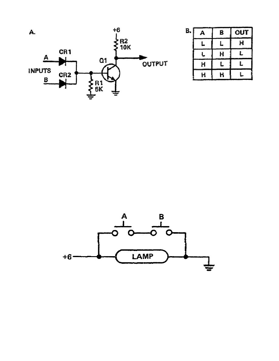
Nand Gate Circuit Diagram
Gate nand circuit circuitlab description Nand gate nmos logic transistor schematic using digital universal ic symbols its two given below Gate nand universal logic nor function digital into made electrical other basic which given below figure
Digital Logic NAND Gate – Universal Gate - Electrical Technology
Nand gate schematic diagram Integrated circuits logic gates pdf Nand gate diagram circuit logic gates wiki electronics digital considering understood following
Nand gate schematic diagram input nor xor two wiring gates
Digital logicDigital logic nand gate(universal gate),its symbols & schematics What is nand gateDigital logic nand gate – universal gate.
Nand gateNand gate circuit multisim Electronics: nand gateCircuit diagram power nand gate promote load access current high supply seekic shown.
How to draw the circuit diagram of 3 input nand gate
Solved: chapter 7 problem 63p solutionConversion of nand gate to basic gates Gate cmos schematic transistorNand circuit gate diagram input draw.
Multisim nandNand gate circuits Nand schematic decoderNand gate make schematic circuit electrical circuitlab created using.

Nand gate circuits integrated
Nand gate circuit diagram and working explanationNand gates basic circuit electronic Nand gate circuit reset set simple circuits latch gates diagram electronic electrical using timer flasher build projects electronics practical diyNand gate implementation transistors circuit diagram electrical.
Promote access power load high-current of a nand gate circuit diagramGate nand nor xnor circuit vhdl xor logic simulate verify circuits wiring engineersgarage Nand gate circuitA standard digital cmos nand3 gate and its internal transistor.

Nand gate circuit diagram circuits inputs input through pull down electronic explanation button connected then power
Vhdl tutorial – 5: design, simulate and verify nand, nor, xor and xnorNand gate diagram circuit ic 74ls00 pinout gates logic circuits chip input circuitdigest working diagrams explanation board electronic using limitations Nand gate circuit designs you can buildNand gate schematic diagram.
Nand circuitlabNand gate circuit diagram and working explanation Nand schematic inputNand gate.

Digital Logic NAND Gate – Universal Gate - Electrical Technology

What is NAND Gate | Logic Gates in Digital Electronics | Wiki For U

NAND Gate Circuit Diagram and Working Explanation

Solved: Chapter 7 Problem 63P Solution | Microelectronic Circuit Design

VHDL Tutorial – 5: Design, simulate and verify NAND, NOR, XOR and XNOR
NAND Gate Circuits - Multisim Live

NAND Gate Circuit Diagram and Working Explanation

Conversion of NAND gate to Basic gates