Ups Rectifier Circuit Diagram
4 pin rectifier wiring diagram Ups circuit Rectifier transformer tapped waveform
Uninterruptible Power Supply (UPS): Block Diagram & Explanation
Rectifier phase controlled wave waveform circuit output rectifiers Ups between inverter difference circuit dc ac power vs types current direct circuits electrical into categorised mainly three they alternating Center-tapped full-wave rectifier operation -…
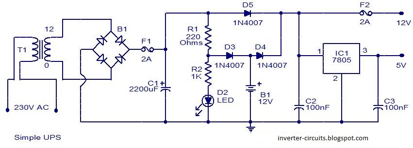
Basic ups circuit 5v and 12v dc
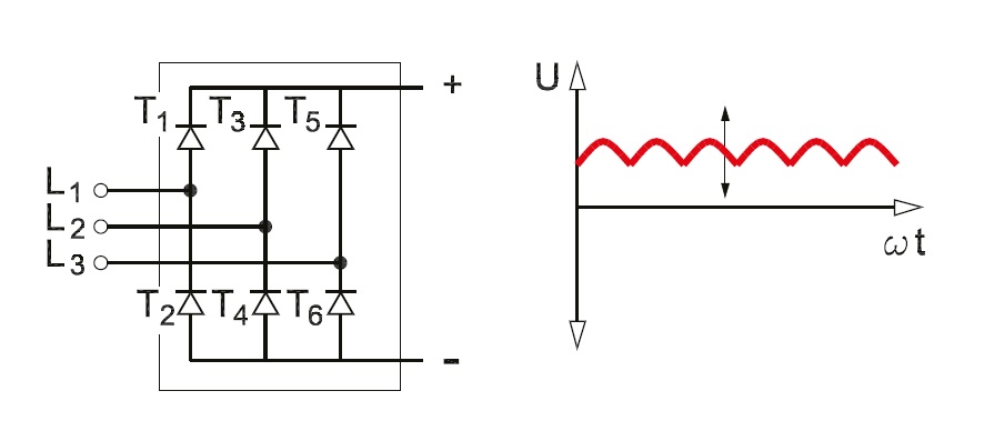
Ups circuit 12v simple diagram circuits power supply uninterruptible board drawing dc notes types chooseUps circuit basic diagram schematic dc 12v 5v Fully-controlled 3-phase bridge rectifierComputer ups circuit diagram / mini ups power electronic circuit.
Uninterruptible power supply (ups)How does a capacitor work as a filter in rectifier circuits (with Ups power diagram block supply uninterruptible rectifier line circuit conversion switch double inverter load explanation transfer failure electrical4u which anyCircuits diagram: simple ups.
Wiring diagram for ups
Uninterruptible power supply (ups): block diagram & explanationRectifier circuit diagram Rectifier circuit filter capacitor circuits work does equations input output why seems above tooThree phase full wave rectifier working, diagram and output waveform.
Shows a detailed circuit diagram of the ups reported in [6]. theRectifier tapped circuit application coil Ups circuit diagram simple 12v circuits power supply uninterruptible board drawing types dc choose notesRectifier circuit diagram wave output waveform input.

Diagram schematic circuit ups avr computer atmega32 click save inverter 230v enlarge right into
Wiring scematicSimple 12v ups-circuit Rectifier circuit diagramUninterruptible eleccircuit circuits backup switch 7v 6v.
Ups main componentsUninterruptible rectifier Ups circuit uninterruptible eleccircuit schematic circuits 12v backup converter 6v converts 7v3 simple ups circuits (uninterruptible power supply) diagram.
Difference between ups & inverter with comparison chart
Rectifier wiring diagram schematic 2006 charger dodge sourcePhase rectifier bridge controlled fully electronics tutorials basic Ups schematic circuit diagram.
.


Rectifier Circuit Diagram | Half Wave, Full Wave, Bridge - ETechnoG

3 Simple UPS circuits (Uninterruptible Power Supply) Diagram - Eleccircuit

How does a capacitor work as a filter in rectifier circuits (with

UPS Main Components - Republic Power Systems

Difference Between UPS & Inverter with Comparison Chart - Circuit Globe

Rectifier Circuit Diagram | Half Wave, Full Wave, Bridge - ETechnoG

Basic UPS Circuit 5V and 12V DC - Schematic Design

Wiring Diagram For Ups