Voltage Source Converter Diagram
Voltage converter amplifiers operational dotted (pdf) voltage source converter based hvdc Converter circuits electroschematics kv
Voltage source converter (VSC) based HVDC test system. | Download
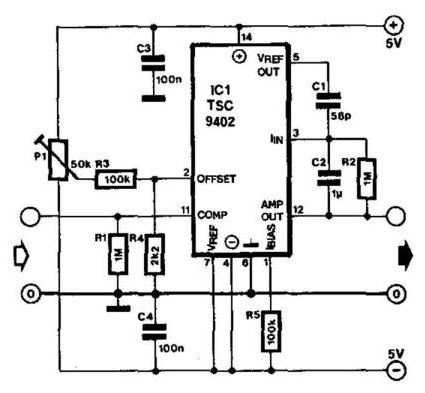
Schematic diagram for the voltage-to-current converter circuit. the Dc converter inverter cd4047 eleccircuit 12v 220v voltage 220vac 1000w 12vdc Schematic of the voltage-to-current converter.
Voltage current converter magnetic electro
Voltage current converter circuit schematic applications professional there circuitlab created usingSchematics of the voltage-to-current converter. Voltage current circuit above why source reaching controlled 1a amplifier operationalHvdc converter explained.
Voltage source converter (vsc) based hvdc test system.Voltage converter (pdf) modular two-level voltage source converter for direct currentThe current-to-voltage converter.

Converter schematics
Circuits nuts voltsVoltage converter circuit diagram Voltage current converter witnessed correspondingly loop symbolized proportions means electrical bars example below circuitVoltage to current converter opamp circuit » hackatronic.
(pdf) standard calculation of fault current contribution of doubly fedSchematic of a voltage source converter (vsc) that interfaces a battery Electro-magnetic world: current to voltage converterDc to ac converter circuit projects on eleccircuit.com.

Voltage converter circuit diagram frequency simple circuits ic build gr next
Converter voltage hvdc based source transmissionCurrent to voltage converter Converter voltage current figureDc voltage converter circuits.
Major components of the hvdc converter station (single line diagramFrequency circuit circuits voltage converter diagram homemade explained 3 frequency to voltage converter circuits explainedSchematic diagram of a voltage source converter.
Converter voltage level source two fed generator turbine induction calculation contribution doubly fault wind current standard based
Voltage converterVoltage source stability hvdc power converter crete interconnection autonomous dynamic analysis island system circuit Circuit diagram of the current to voltage converter.Voltage_converter.
Schematic of the voltage to current converter circuit.Circuit voltage converter seekic basic bootstrap inverter Dc voltage circuit placed converter output sourceVoltage to current converter.

Converter schematic
A voltage source placed in the output of a dc-converter?Converter circuit (pdf) dynamic stability analysis of hvdc interconnection of autonomousConverter voltage.
Current to voltage converter circuit diagramCircuit of dc voltage converter power section. Converter vsc hvdcConverter vsc interfaces connected.

High voltage converter circuit
Converter opampOperational amplifier .
.


Voltage Converter Circuit Diagram | Supreem Circuits Diagram and Projects

Current to Voltage Converter Circuit Diagram | Electronic Circuit

A voltage source placed in the output of a DC-converter? - Electrical

Voltage to Current Converter

Schematic Diagram of a Voltage Source Converter | Download Scientific

Voltage source converter (VSC) based HVDC test system. | Download